
Plan the integration and coordination of energy systems, including electricity, gas, and thermal networks.

Plan for the Future of Electricity
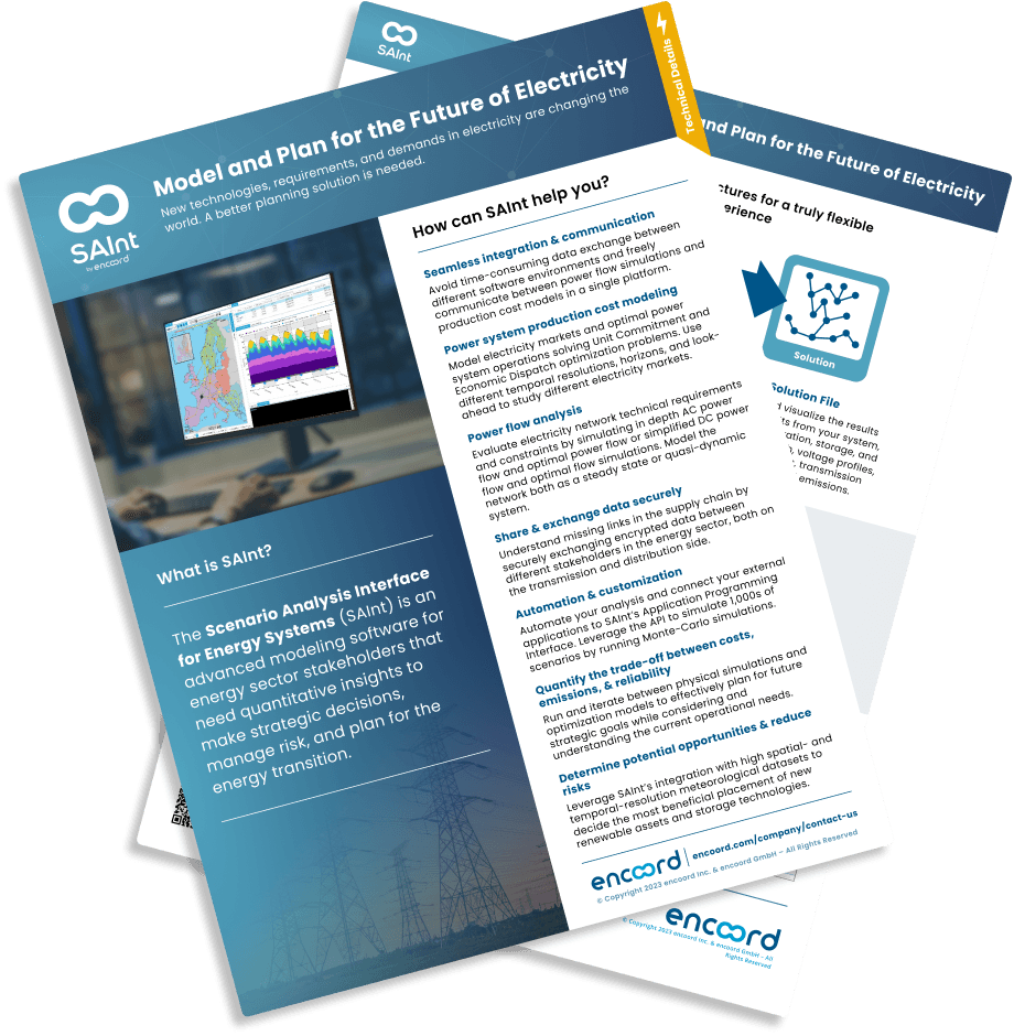
New technologies, requirements, and demands in electricity are changing the world. A better planning solution is needed.
The challenges the industry is facing
Integration of renewable generation and storage technologies
New technologies are arriving at an unparalleled pace. How do you choose the best path forward?
Operational and strategic planning should be coordinated
Strategic planning without consideration of operational realities increases costs and risks. Operational planning without strategic guidance slows growth.
EVs, DER, DR, AMI - the alphabet soup of planning requirements
Innovation brings opportunities to enable the energy transition while it challenges planning teams.
Time and cost
Multiple planning platforms and data sources increase cost and time while reducing trust in the decision process.
Planning for decarbonization
What is the most efficient, effective, and economic path to decarbonization?

How encoord provides the solution
SAInt - An Integrated Systems Modeling Platform
The Scenario Analysis Interface for Energy Systems (SAInt) is a software platform designed to model integrated energy networks and markets.
Electricity Network Modeling
Model electricity transmission and distribution networks.
Energy Market Modeling
Model electricity and other energy markets.
Services
encoord provides advisory, training, data, and support services to help you implement SAInt and better plan for the energy future.
Model-Ready Datasets
We provide SAInt users with model-ready datasets of energy networks & markets.

Want the technical flyer?
Check out our flyer on electricity planning to learn more.
See how to plan for...

Gas
The future of gas is uncertain and effective planning will be necessary to understand and enhance the role of gas infrastructure in the energy transition.

Hydrogen Integration
Alternative fuels cause their own mix of challenges. How do you plan for greener fuels?

Renewable and Storage Integration
Renewable generation and storage technologies can cause as many problems as they solve. Careful scenario planning is required to quantify and minimize risk.

Thermal Networks
Heating and cooling demands are large and represent potential sources of flexibility. How do you plan the future of thermal networks?